Page 1 of 6 123 ... LastLast
Results 1 to 10 of 58

Thread: Analyzing log files

Hybrid View

Previous Post Previous Post   Next Post Next Post
  1. #1
    Lifetime Member Rich Z's Avatar
    Join Date
    Mar 2006
    Posts
    291

    Default Analyzing log files

    I'm spending a lot of time (relatively speaking, of course) just reviewing the log files I've been accumulating while getting my toes wet with EFILive. I figure that unless I understand what I am actually SEEING during a logging session, then trying to jump right in with tuning will be a fruitless and frustrating experience. But quite honestly, I don't have any sort of yardstick to go by to compare my logs with to try to figure out if what I am seeing is good, OK, or just plain awful.

    For instance, I don't see any signals from the PIDs for long term fuel trims. Do I have something set up incorrectly in the setup for data capture?

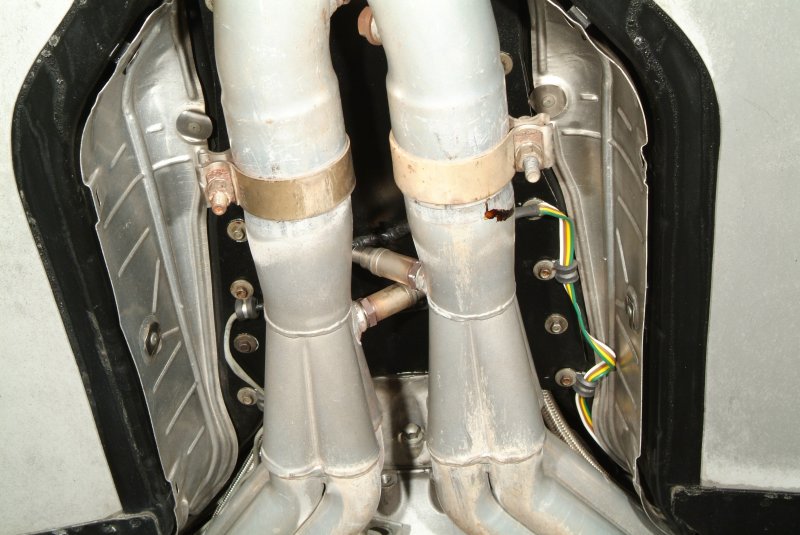
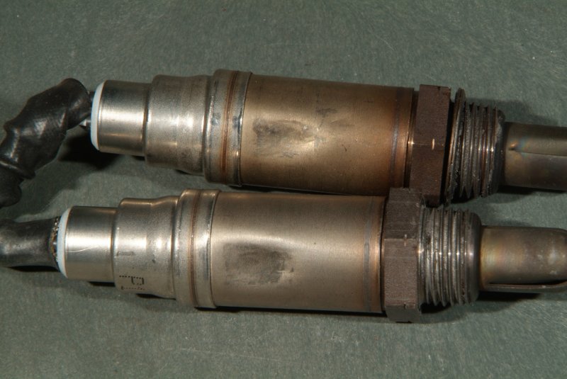
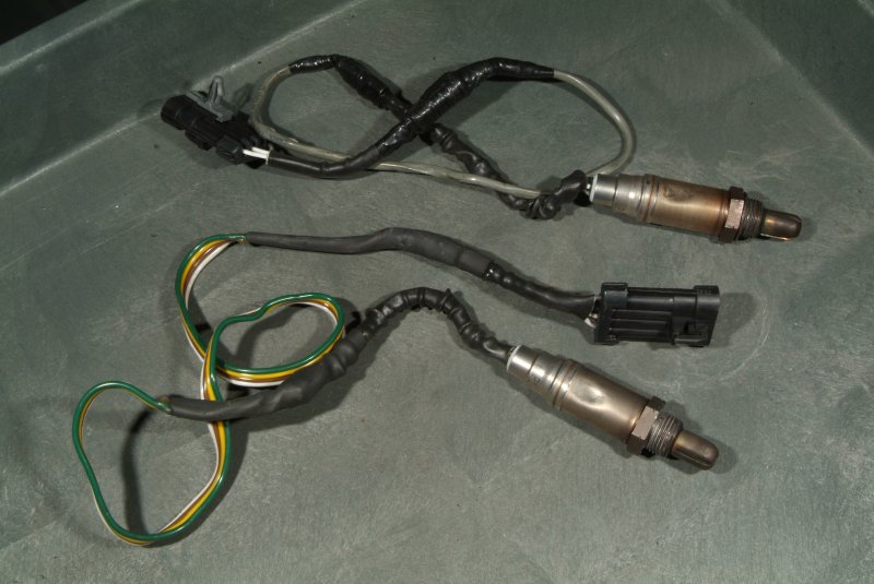
    My O2 sensors seem to be working OK, I think, which surprised me since I thought the harness on at least the passenger side one had been butchered. But is the signal I see during acceleration and deceleration normal? It looks like pretty much a nice sine wave during constant speed cruising.

    The AFR from my wideband seems to be a low amplitude sine wave centered around the commanded AFR. But there are spikes and dips with RPM and TP changes. How much variation is "normal"?

    My SAE.MAF signal doesn't seem to climb past the half way mark in my dashpage display. Is that normal?

    My MAP inHg signal is hitting over 100 in spots. Is this normal for a 2 BAR MAP with FI? Am I really seeing vacuum or seeing pressure?

    The MAX I have seen on my injector duty cycles is 15 percent during normal driving. Is that OK?

    With my foot off of the gas pedal, I see a throttle position of 17.3 percent. Does that sound right?

    While crusing down my dirt road at 10 mph, my SPARK Deg trace looks like a snake trying to dodge getting run over. Should it be this way or be a fairly stable line?

    Referring to above, my RPM jumps around quite a bit, from around 885 to 1030 at low speed with no pressure on the gas pedal. Is that normal?

    In other words, can someone point me to some yardsticks I can compare to what I am seeing? Or maybe look at my own log files to perhaps point out some things that just seem odd to you?

    Oh yeah, and what is this CALC.POWER_RW value? I see a max value of 867 when the max RPM I hit that trip was only 3354. So that certainly can't be correct. I would think my rear tires would be shredding off of the wheels if that were true.

    Anyway, thanks for any guidance you all can give me on this.

    CorvetteFlorida.com

    2002 Corvette Z06
    427 RHS block built by LME
    STS rear mounted twin turbos
    It nearly died on the operating table, but I'm bringing her back.

  2. #2
    Joe (Moderator) joecar's Avatar
    Join Date
    Apr 2003
    Posts
    28,403

    Default

    Rich,

    Post some log files.

  3. #3
    Lifetime Member Rich Z's Avatar
    Join Date
    Mar 2006
    Posts
    291

    Default

    OK, done. Bear in mind that I live on a dirt road, so the first log should be of my driving under 10 mph. The odd thing about that log is how the RPMs jump all around, and the jagged trace that the timing makes. Also, I think it's in the third log that you will see the 6 seconds where my IAT reading went bonkers.

    I'm using the serial interface from my LC-1 wideband, btw.

    Thanks....
    Attached Files Attached Files

    CorvetteFlorida.com

    2002 Corvette Z06
    427 RHS block built by LME
    STS rear mounted twin turbos
    It nearly died on the operating table, but I'm bringing her back.

  4. #4
    Lifetime Member Rich Z's Avatar
    Join Date
    Mar 2006
    Posts
    291

    Default

    Quote Originally Posted by Rich Z View Post
    Also, I think it's in the third log that you will see the 6 seconds where my IAT reading went bonkers.
    I was planning on taking the car out for a drive today after fixing a bunch of minor exhaust leaks, and I had the laptop on, running EFILive, and was logging the warm up cycle to note how it goes from open loop to closed loop. I noticed immediately that the IAT signal was pegged at 284 degrees and staying there. So I apparently had a SOLID failure to track down. The main reason I was going to take the car out today was to do some logging specifically for this IAT problem. I had cleaned the contacts on the connector thoroughly, so I wanted to see if maybe that corrected the problem. Apparently not. Turns out I was barking up the wrong tree anyway.

    So I shut off the car and set up the laptop where I could watch it while I was poking around under the hood with that harness. Connie was actually monitoring the screen for me, and she called out when the signal dropped from 284 to 90 degrees or so while I was jiggling a particular section of the IAT/MAF cable harness. So it looked like we had zeroed in to the problem. Hard failures are SO much easier to find than intermittent crap.

    So I pulled the insulation sleeve off of the harness to take a look. And here we go:


    Whoever did this piss poor soldering job left jagged ends sticking out from the soldered joints, and didn't bother to even cover the purple wire individually. Just plain laziness. So what happened was that a sharp point on the purple wire's joint had cut right through the insulation on the yellow wire and was shorting the two of them together. There were a couple of other sharp points on the other wires, so they may have been poking through the insulation as well. If not now, certainly sometime in the future.

    Two things really wrong with this solder job. (1) Before putting the shrink wrap on the solder joints, smooth the sharp solder points down. This can easily be done with no more than needle nose pliers by crimping them down flat against the wire. Actually wrap the two wire ends together properly, and you rarely have sharp points sticking out every which way. (2) With multiple wires being soldered in a harness, stagger the cuts on the wires so the joints aren't right next to a neighboring joint. This not only helps to prevent this kind of problem with shorts, but also keeps you from having a big LUMP in a harness when you try to put a cover over the entire wiring. You know, looks like a snake that ate a big rat or something.

    So I crimped the sharp ends in the solder joints, then rewrapped them all with silicon tape. Double checked the signal to make sure the short was gone, then rewrapped the entire harness with insulation and wire wrapped it back in place along the air bridge.

    So I believe the intermittent IAT problem has been solved now as well.

    Maybe tomorrow I can take the car out for a spin. I didn't hook the wideband controller up again, as I want to burn off any anti-seize compound that might be in the exhaust pipes above the sensor first.

    CorvetteFlorida.com

    2002 Corvette Z06
    427 RHS block built by LME
    STS rear mounted twin turbos
    It nearly died on the operating table, but I'm bringing her back.

  5. #5
    swingtan
    Guest

    Default

    1. LTFT PIDs appear to be there so I guess you have not selected them for the charts you are viewing. If you "Right click" on a PID label on the sides of a chart, you get an option to select a new PID. Look under the "Other PIDs" listing for the LTFT's.
    2. The O2 voltages indicate that one of the sensors may have a damaged heater feed. It looks like it takes longer to become active and when it does, it's slightly lazy. It may be wiring or it may just be a bad sensor.
    3. Variation for the O2 sensor is arbitrary. A good check is to compare both O2's to see how similar that look. They shouldn't be "identical" when viewed over a time period, but should appear similar.
    4. The MAF signal is just a measurement displayed on the chart. The total air flow is what ever the motor is using, the level on the graph can be adjusted by right clicking on the chart and selecting "chart properties". Read the help files for adjusting chart properties.
    5. 100 inHg, I'm not sure where you are measuring that. 100kPa is normal barometric pressure, are you mixing up inHg and kPa?
    6. Injector Duty Cycle peaks only really come into play at peak engine torque. As long as you are at a reasonable level here (80% to 90%) then other load points should be fine.
    7. Is this a cable throttle or electronic? The ETC will hold the throttle open on declaration.
    8. Spark at low RPM could just be a steep ramp in the spark map. It may be nothing and if the car drives OK, Then it's not a huge issue. It could also just be torque management in the auto.


    It's probably worth you reading through the tutorials and help files. Even better, get on to one of the EFILive courses.

    Simon.

  6. #6
    Lifetime Member Rich Z's Avatar
    Join Date
    Mar 2006
    Posts
    291

    Default

    Quote Originally Posted by swingtan View Post
    1. LTFT PIDs appear to be there so I guess you have not selected them for the charts you are viewing. If you "Right click" on a PID label on the sides of a chart, you get an option to select a new PID. Look under the "Other PIDs" listing for the LTFT's.

      The PIDs I have selected are
      • Long Term Fuel Trim - Bank 1 (SAE.LONGFT1)
      • Long Term Fuel Trim - Bank 2 (SAE.LONGFT2)

    2. The O2 voltages indicate that one of the sensors may have a damaged heater feed. It looks like it takes longer to become active and when it does, it's slightly lazy. It may be wiring or it may just be a bad sensor.

      Could be wiring, as there appear to be wires in the harness for the passenger side O2 sensor that look like they were cut off, and possibly others spliced in place.

      When I got my car back from the shop that worked on it, this is what I saw for the O2 sensor wiring:


      Notice the trailer hitch wire on one side, and the radio shack wire on the other.

      Then I replaced both O2 sensors when I noticed them looking like this:


      So yeah, ANYTHING is possible.

    3. Variation for the O2 sensor is arbitrary. A good check is to compare both O2's to see how similar that look. They shouldn't be "identical" when viewed over a time period, but should appear similar.

      Well, I'm guessing they are basically OK then. Except for the possible slow heat-up you mentioned. I'm assuming "bank 1" refers to the engine side where cylinder number 1 resides?
    4. The MAF signal is just a measurement displayed on the chart. The total air flow is what ever the motor is using, the level on the graph can be adjusted by right clicking on the chart and selecting "chart properties". Read the help files for adjusting chart properties.

      Well the chart says MAF Lbs/min (SAE.MAF). I'm pretty much just using a very slightly modified DEFAULT dashboard and PID selection. I do have twin rear mounted turbos on the car, but I don't think I went into boost during this drive. So I guess the question is how accurate the MAF signal will be under full boost? And does the air flow characteristics change substantially even when under full boost as I would think the turbos would change things somewhat even during normal driving.
    5. 100 inHg, I'm not sure where you are measuring that. 100kPa is normal barometric pressure, are you mixing up inHg and kPa?

      Heck if I know. I'm looking at the data tab and seeing "Intake Manifold Absolute Pressure" with the Units showing as "PSI" (SAE.MAP). But that surely can't be the units being displayed in the dashboards. The PID itself shows units in "kPa,PSI" so beats the heck out of me what I might have done wrong here.
    6. Injector Duty Cycle peaks only really come into play at peak engine torque. As long as you are at a reasonable level here (80% to 90%) then other load points should be fine.

      I guess what caught my attention is how LOW those readings are. Granted I really didn't "get on it" during this run, but they showed a max of just 15 percent. I'll have to see if I have a log where I ran the engine up to 5,000 rpm or so to see what that shows.
    7. Is this a cable throttle or electronic? The ETC will hold the throttle open on declaration.

      Electronic. This is a 2002 Corvette Z06 with a custom 427 in it. STS twin turbos, F.A.S.T. 102 intake, C6 Z06 throttle body (silver blade), long tube headers.
    8. Spark at low RPM could just be a steep ramp in the spark map. It may be nothing and if the car drives OK, Then it's not a huge issue. It could also just be torque management in the auto.

      At low RPMs driving down my dirt road the spark advance looks like a saw blade. Granted I know my tuner didn't really spend much time at all on the low RPM stuff, but I think it is something that does need some work. The car does often surge while driving at under 10 mph.


    It's probably worth you reading through the tutorials and help files. Even better, get on to one of the EFILive courses.

    Yeah, been doing that. And reading through old threads here as well. I know I'm a raw newbie, but everyone says I just need to ask questions. So here I am.

    Simon.
    Thank you for your help with this.

    CorvetteFlorida.com

    2002 Corvette Z06
    427 RHS block built by LME
    STS rear mounted twin turbos
    It nearly died on the operating table, but I'm bringing her back.

  7. #7
    Lifetime Member Rich Z's Avatar
    Join Date
    Mar 2006
    Posts
    291

    Default

    BTW, to give you a REAL good idea about why I don't trust anythign in the wiring for my O2 sensors, get a load of this:


    When I asked the guy about this, he says that's the way he does all the wiring for O2 sensors on cars that come into his shop. Obviously his shop will never see my cars in there again.

    CorvetteFlorida.com

    2002 Corvette Z06
    427 RHS block built by LME
    STS rear mounted twin turbos
    It nearly died on the operating table, but I'm bringing her back.

  8. #8
    Joe (Moderator) joecar's Avatar
    Join Date
    Apr 2003
    Posts
    28,403

    Default

    From swintangs comments and your replies:

    1. did you select the pids LONGFT1/2...? did you place these on a chart...?

    2. that O2 wiring is not acceptable.

    5. use the units kPa (scantool: PIDs tab, on MAP do rightclick->Metric; tunetool: Edit->Configure Display Units, look at B0101).

    7. for electronic throttle, look at the pid GM.ETCTP.

    When selecting pids, make sure the pid channel count is no greater than 24.

    I'm on the Mac so I can't view the log files right now, I'll view them later tonite.

  9. #9
    Lifetime Member Rich Z's Avatar
    Join Date
    Mar 2006
    Posts
    291

    Default

    Quote Originally Posted by joecar View Post
    From swintangs comments and your replies:

    1. did you select the pids LONGFT1/2...? did you place these on a chart...?

    Yes, as best I can tell. I went though all of my logs and looked at the PIDS, DATA, and dashpages, and they are there.

    2. that O2 wiring is not acceptable.

    You don't know a tenth of what my car went through. Well, maybe you do if you have looked over that thread I pointed you to.

    5. use the units kPa (scantool: PIDs tab, on MAP do rightclick->Metric; tunetool: Edit->Configure Display Units, look at B0101).

    I'll be honest, I really don't remember how I may have set this up or changed it. kPa just doesn't compute quite yet with my old SAE brain.

    7. for electronic throttle, look at the pid GM.ETCTP.

    I'm using Absolute Throttle Position (%) as far as I can tell. SHOULD throttle position be ZERO when my foot is off of the gas pedal?

    When selecting pids, make sure the pid channel count is no greater than 24.

    It looks like I have 22 PIDS selected in my log files.

    I'm on the Mac so I can't view the log files right now, I'll view them later tonite.
    Going to be a few days before I will have my car back on the street again. I'm putting in PTFE fuel lines and replacing those stinking rubber lined ss braided lines that were put on my car. Those rubber lines seep gasoline through them like it's no body's business. You can actually see the gasoline stains with UV light.

    Thanks for your help.

    CorvetteFlorida.com

    2002 Corvette Z06
    427 RHS block built by LME
    STS rear mounted twin turbos
    It nearly died on the operating table, but I'm bringing her back.

  10. #10
    EFILive Developer Site Admin Blacky's Avatar
    Join Date
    Mar 2003
    Posts
    9,516

    Default

    Quote Originally Posted by Rich Z View Post
    I'm using Absolute Throttle Position (%) as far as I can tell. SHOULD throttle position be ZERO when my foot is off of the gas pedal?
    The corvette, with its ETC (electronic throttle controller), holds the throttle blade open to control idle air flow. So even when there is no pedal input the throttle blade will be slightly open to allow enough air to enter the engine to keep it idling.
    For vehicles with a cable throttle, the throttle body usually has a bypass called the IAC (Idle Air Control) which the PCM uses to control the idle air flow while the throttle blade is shut.

    Regards
    Paul
    Before asking for help, please read this.

Page 1 of 6 123 ... LastLast

Similar Threads

  1. log files
    By zbadestz in forum 6 speed/8 speed RWD/FWD Transmission Tuning (incl T43, T76, T87)
    Replies: 0
    Last Post: April 20th, 2012, 10:59 AM
  2. A few log files - everything look okay?
    By Y2KsilverTA in forum Gen III V8 Specific
    Replies: 0
    Last Post: November 8th, 2011, 10:56 AM
  3. What's going on with my log files?
    By DrX in forum General
    Replies: 7
    Last Post: December 7th, 2009, 04:41 PM
  4. Merging Log Files?
    By Cougar281 in forum General
    Replies: 1
    Last Post: July 7th, 2008, 01:27 PM
  5. Editing log files
    By Gelf VXR in forum General (Petrol, Gas, Ethanol)
    Replies: 2
    Last Post: March 12th, 2008, 04:55 AM

Posting Permissions

  • You may not post new threads
  • You may not post replies
  • You may not post attachments
  • You may not edit your posts
  •