


EDIT: Sorry for the wide pics, I have a widescreen monitor.
For the first time I switched from open loop speed density to closed loop speed density. I figured I might pick up a mpg or two by doing so.
I during my last fine tune of my VE talbe I did some minor tweaking. I did probably an 1.5 hour drive hitting a lot of the cells. The corrections were small.
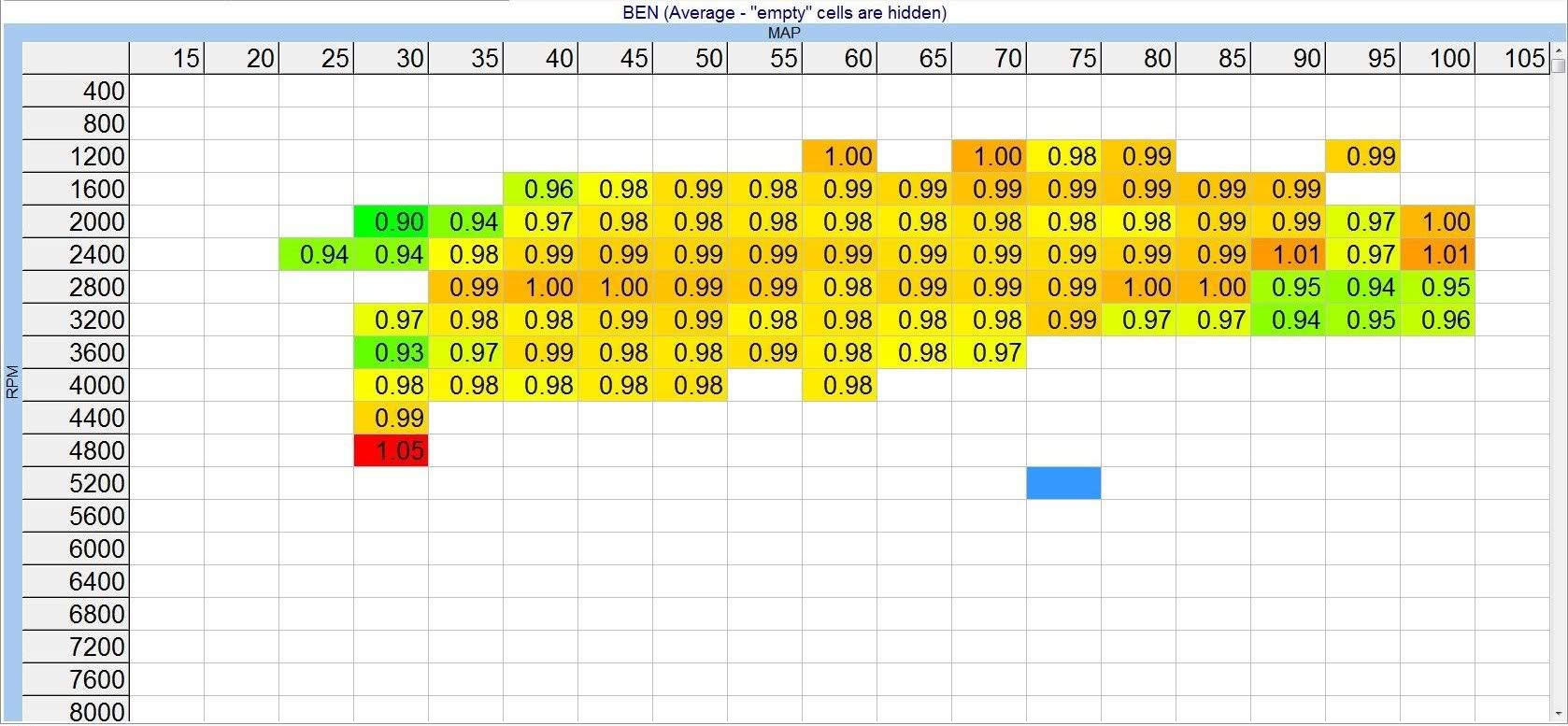
Here you can see my BENs from my logging process. In this screen shot I'm hiding cells with lower than a cell count of 50, and filtering the data. Most cells have 100 counts or more. Many of the cruising cells have 1000 data points.
Then I took that BEN data, applied it, and did some smoothing. I also used some WOT pulls and hard engine deceleration logs to get the cells you cannot sit at steady state.
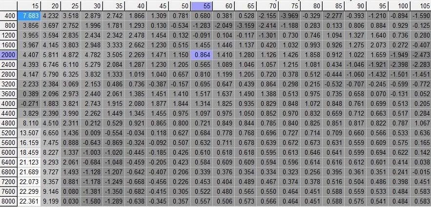
This is a screen shot of the % change from the tune while logging, to the new tune I just loaded. As you can see, in the main part of the map where you'd be cruising the % changes are very small, and very close to the BENs from the logging. Positive numbers mean that I corrected it in the leaner direction, just as the BENs told me to do.
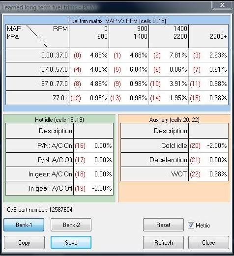
So I took that new map, put it into a new tune. Then I turned on the closed loop fueling, and turned DFCO back on. Went out and drove maybe 5 seperate times, for a total of 2 or so hours of driving. Then I took a screen shot of my long term fuel trims for bank 1 and bank 2. I am very very confused by how far positive they are.
Here are the LTFTs
Bank 1
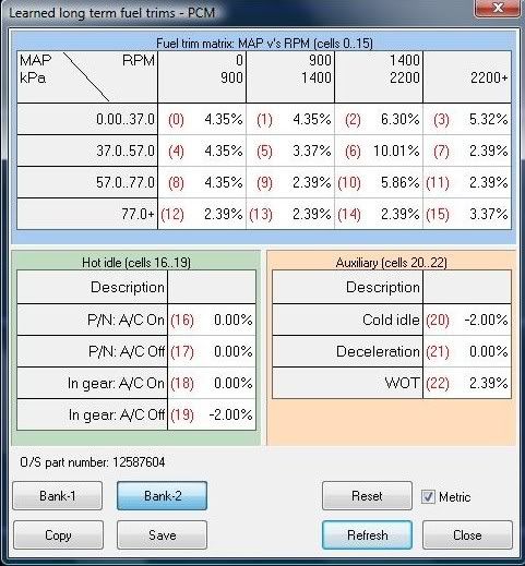
Bank 2
When I look at some logs to see what the wb02 says its doing in closed loop I see that the BENs come out to about 0.98. I'm really confused on what is going on here. When cruising I see that the FUELSYS says that I'm in CL-Fault mode, and switches to OL when I get on the gas heavy. Is CL-Fault mode correct for a speed density setup? I'm thinking it is, but not sure.
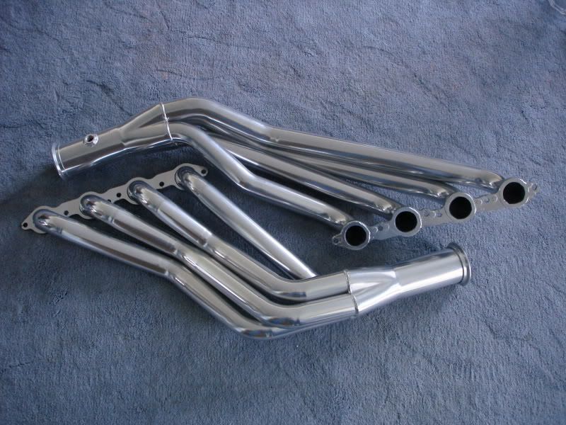
My setup consists of basically a big cam only motor. I have long tubes, 3" exhaust w/o cats, and a dual 3.5" intake. Pretty basic setup. I have a texas speed MS4 cam.
I'm not sure what is going on these trims, and why they say my maps are sooooo lean. Any help or input here would be greatly appreciated. Also, my WOT is spot on now, and I don't want any stupid trims to be added to them making it overly rich.
I have attached many files. Here is a description of the files I've attached.
5-3-2008_002.tun is the baseline tune I was using when I did the VE BEN logging.
5-4-2008.tun is the new tune that I created from the logged BENs. I also switched to CLSD, and turned DFCO back on.
5-4-08 VE BEN main.efi is the long log from my VE BEN logging.
5-7-08 Work Commute 2.efi is a ~20 minute drive to work. Following this last drive is when I took the screen shots of the LTFTs.

 Reply With Quote


 The Tremor at AIR

 Assuming you monitor based on which CL Mode you're in, I don't see why not.
