You are well into a
major science project. There a many factors involved in getting a smooth laminar airflow. Without a degree in the subject, it will be a frustrating trial and error process.
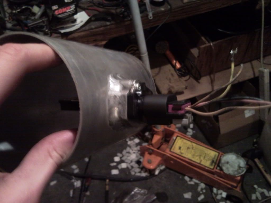
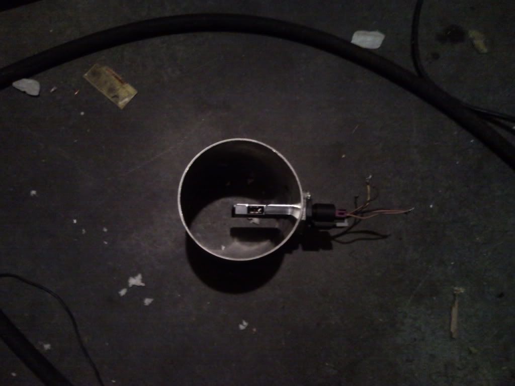
First, the GM Hitachi element is far superior to anything pervious so you are off to a good start. You can try to picture in your mind what the airflow looks like across the tube. You want that sensor opening in a non turbulant, smooth stable, location in the airflow path. This is VERY sensitive and minor changes make a huge difference.
From here it looks like you need to increase the the thickness of your elemnt mount to cause the element tip move closer to the inner wall of the tube.
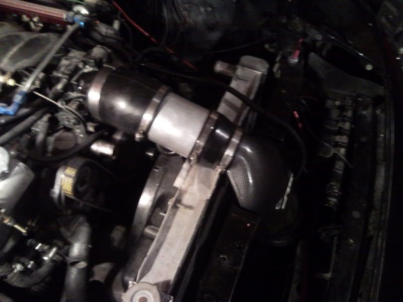
Another factor is the transitions you have just before and after the MAF. The air is being steered and the air velocity across the tube is changing. Ideally, all the pieces should be the same size and shape so as to have the same effective square inch area.
Jim Hall of Halltech, and I are months into developing an CAI intake with MAF for the new Camaro and we have made dozens of changes trying to achieve a smooth, even airflow. Even an eighth inch diameter change will cause a dramatic change in airflow. Very minor changes can net positve or negative results on the dyno. Often a minor change will net lower dyno numbers than even the stock intake. Bigger is often, not better.
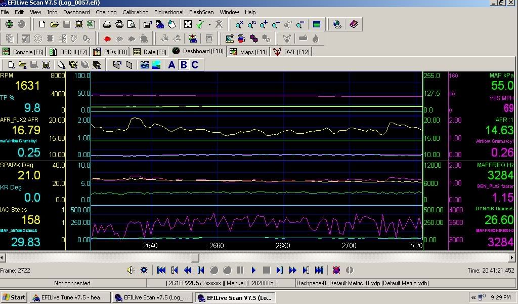
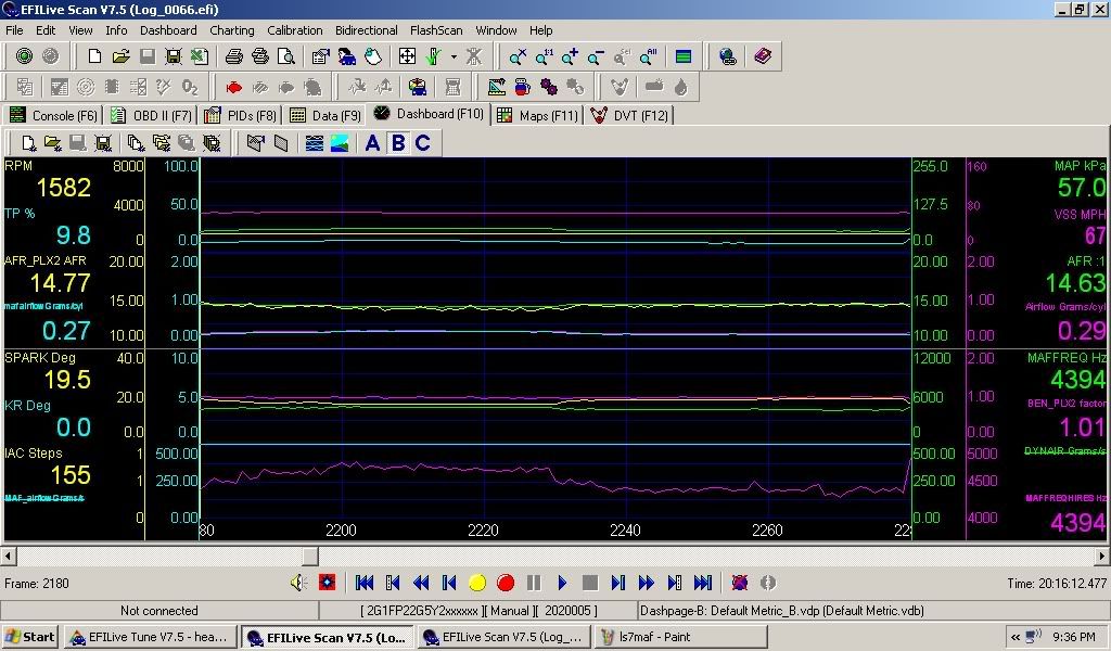
Watch your fuel trims at a constant low rpm to see the difference between different configurations.
Bruce
the PowrMAF guy


 Reply With Quote


