Page 1 of 2 12 LastLast
Results 1 to 10 of 14

Thread: DYNAIRTMP.DMA Experiment..Is it Indeed Charge Temperature?

  1. #1
    R.I.P Shawn, 1956-2011 WeathermanShawn's Avatar
    Join Date
    Jul 2008
    Posts
    1,807

    Default DYNAIRTMP.DMA Experiment..Is it Indeed Charge Temperature?

    Is DYNAIRTMP.DMA indeed the actual Charge Temperature found in the EFILive VE Table calculation.

    Charge Temperature is defined as 273.15+IAT+((ECT-IAT)*factor) where factor is obtained from Tables B4901 Charge Temperature Blending and Table B4902 Charge Temperature Filter.

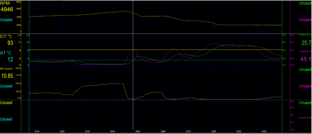
    I did a series of log where I kept ECT & IAT constant. Only MAF Airflow changed. I logged DYNAIRTMP.DMA and a Calculated DYNAIRTMP using Table B4901. The DYNAIRTMP.DMA shows a more blunted rise/fall in temperatures in rapid MAF Airflow changes than utilizing the DYNAIRTMP alone.

    I have checked for scanning lags (can't find any) and double-checked my math and Look-up Tables and the data appears accurate.

    Does this prove that DYNAIRTMP.DMA is utilizing both B4901 and B4902 and is indeed the 'true' charge temperature or am I missing something?

    Last edited by WeathermanShawn; March 1st, 2011 at 09:38 AM. Reason: Updated Attachments..
    2002 Black Camaro Z-28 M6 Hardtop 11.0:1CR 425HP/410TQ SAE (400TQ@3500RPM)
    200cc Heads, 228/232 110+2 Cam, 1 3/4" LT's w/catts, GMMG, Koni Shocks, Hotchkis Springs, 35/21 Sways, 17" ZR1's, 3.90 Gears Roadrunner PCM LM-2 Serial Wideband
    EFILive Closed-Loop MAF/SD Hybrid Tune..


  2. #2
    Joe (Moderator) joecar's Avatar
    Join Date
    Apr 2003
    Posts
    28,403

    Default

    Hi Shawn,

    It shows that the PCM/OS is using B4901 and B4902 and probably something else (which we don't know about)...

    Blunted rise/fall:
    looks like the PCM is filtering the rate of change (slowing it down) [I wonder how it uses B4902...?];
    when CALC.DYNAIRTMP reaches a (fairly) stable value then GM.DYNAIRTMP_DMA catches up to it (the same value)...

    This shows GM put some serious R&D into modeling DAT.


    This experiment also shows that while ECT and IAT are constant, other factors (such as airflow) influence DAT.

    Very interesting experiment...

  3. #3
    R.I.P Shawn, 1956-2011 WeathermanShawn's Avatar
    Join Date
    Jul 2008
    Posts
    1,807

    Default

    Quote Originally Posted by joecar View Post
    [I wonder how it uses B4902...?]
    Mmm..I wonder also..its a rate of change function..similar to acceleration (mathematically)?

    Thanks for looking it over. Pretty much 'proves' that DYNAIRTMP.DMA is the infamous charge temperature. Since we normally filter out large TPS% changes for CALC VE & VET, I don't think it will hurt the Look-Up Tables users that much..

    Interesting though, I'll keep pondering B4902 for now...
    2002 Black Camaro Z-28 M6 Hardtop 11.0:1CR 425HP/410TQ SAE (400TQ@3500RPM)
    200cc Heads, 228/232 110+2 Cam, 1 3/4" LT's w/catts, GMMG, Koni Shocks, Hotchkis Springs, 35/21 Sways, 17" ZR1's, 3.90 Gears Roadrunner PCM LM-2 Serial Wideband
    EFILive Closed-Loop MAF/SD Hybrid Tune..


  4. #4
    Lifetime Member swingtan's Avatar
    Join Date
    Jul 2007
    Posts
    1,589

    Default

    I can't check right now, but there is a filter table for charge temp changes. It would appear (from memory) that low speed air flow changes temp slower than hi speed air.

    Sent from my HTC Desire

  5. #5
    R.I.P Shawn, 1956-2011 WeathermanShawn's Avatar
    Join Date
    Jul 2008
    Posts
    1,807

    Default

    swingtan:

    Here is the premise..GM.DYNAIRTMP.DMA = GM.CHRGTEMP_DMA - Calculated charge temperature based on IAT, ECT, Charge Temp Blending, and Charge Temp Filter.

    Previously it was hard to 'prove' that GM.DYNAIRTMP.DMA (DAT) was exactly the same term as GM.CHRGTEMP.DMA. However this experiment compared two different forms of DAT and so far has indicated that DAT is in fact the 'charge temperature'.

    It gives us more confidence that we are calculating the following charge temperature correctly..

    The PCM calculates the charge temperature (in degrees Kelvin) using the following formula
    273.15+IAT+((ECT-IAT)*factor) where factor is obtained from this calibration.

    What do you think?


    2002 Black Camaro Z-28 M6 Hardtop 11.0:1CR 425HP/410TQ SAE (400TQ@3500RPM)
    200cc Heads, 228/232 110+2 Cam, 1 3/4" LT's w/catts, GMMG, Koni Shocks, Hotchkis Springs, 35/21 Sways, 17" ZR1's, 3.90 Gears Roadrunner PCM LM-2 Serial Wideband
    EFILive Closed-Loop MAF/SD Hybrid Tune..


  6. #6
    Lifetime Member
    Join Date
    Jul 2005
    Posts
    702

    Default

    welcome to 4yrs ago:
    http://redhardsupra.blogspot.com/200...-modeling.html
    http://redhardsupra.blogspot.com/200...ng-part-2.html
    http://redhardsupra.blogspot.com/200...important.html

    Temperature estimators in GM cars are a very nice long story about evolving a mathematical model to increase its precision and make it more resilient to undesired side effects (ie. heatsoak).
    First you had what Shawn is talking about, just the straight up bias based formula.
    Then you have what swingtan is talking about, the lag filter is applied to account for the intake taking time to change temperature, based on amount of airflow going through it.
    Then in the newer ECU's, the bias table been expanded from 2d to 3d to use not only airflow, but also speed of the vehicle (and thus, the speed of the air entering the intake system), to farther increase the precision of the biasing function.
    I haven't looked at the newest stuff, I hope they didn't make it any more complicated than it already is. I've only been able to solve the first scenario, the lag filter is killing me as I don't know what is the time reference it uses. Paul/Ross might have some insight, I hope...

  7. #7
    R.I.P Shawn, 1956-2011 WeathermanShawn's Avatar
    Join Date
    Jul 2008
    Posts
    1,807

    Default

    Thanks Marcin..

    I think Joecar had some insights into how the lag filter is derived. We may all have to dust off our math books to quantify it.

    From a practical standpoint, at least it appears that the DYNAIRTMP.DMA (DAT) expression itself is the product of all of all the biases combined. I.E., its the value you actually want as it appears to be the actual charge temperature. That way really the point of the exercise. Its the value I was looking for.

    It would be productive though to quantify each bias, but putting all that in a calculated pid would take some work. If you are lucky enough to have the DAT.DMA, I think you have the value you are really looking for.
    2002 Black Camaro Z-28 M6 Hardtop 11.0:1CR 425HP/410TQ SAE (400TQ@3500RPM)
    200cc Heads, 228/232 110+2 Cam, 1 3/4" LT's w/catts, GMMG, Koni Shocks, Hotchkis Springs, 35/21 Sways, 17" ZR1's, 3.90 Gears Roadrunner PCM LM-2 Serial Wideband
    EFILive Closed-Loop MAF/SD Hybrid Tune..


  8. #8
    Lifetime Member swingtan's Avatar
    Join Date
    Jul 2007
    Posts
    1,589

    Default

    Quote Originally Posted by redhardsupra View Post
    Then in the newer ECU's, the bias table been expanded from 2d to 3d to use not only airflow, but also speed of the vehicle (and thus, the speed of the air entering the intake system), to farther increase the precision of the biasing function.
    This is an interesting one..... I've been testing this in my E38 as the charge temp tables have a VSS axis. However, I can't get it to make a difference with the speeds listed there. I actually get the feeling that the axis is not really VSS at all but is actually Air speed in gm/Sec. So for me, I think B0179 is labeled incorrectly, though I may have missed another table that influences the changes.

    Simon.

  9. #9
    Lifetime Member
    Join Date
    Jul 2005
    Posts
    702

    Default

    Simon, the easy way to test which part of of the table is working is to artificially change the bias vs speed and airflow table to something extreme, like at 50g/sec i'd make it 0 and everything below 50g/sec I would make 1. Then have one chart that does the DMA value, IAT and ECT in one window. drive gently (under 50), and DMA value should overlap with IAT, above 50g/sec it would overlap with ECT. Of course the fueling will be wrong, so remember to change it back, but this is just for a test to make sure that the table is active, and it indeed takes airflow into consideration. Then you can do another version of this test, and alter the 0 and 1 values along some arbitrary speed value, let's say 50km/hr, and repeat the experiment. Oh, another thing, this experiment would work best if you turned off the lag filter table to instant changes (all values in the filter table =1 if i recall correctly).

  10. #10
    Lifetime Member
    Join Date
    Jul 2005
    Posts
    702

    Default

    Shawn, there are three serious problems with the temp estimator:
    1. calibration--even if we know how the whole model works, in order to calibrate the BIAS and FILTER tables, you need an airmass value. To have that airmass value you need the TEMP. it's a circular reference, and does not have a closed solution, only a iterative nonlinear solver running over parametrized version of BIAS and FILTER. I've had code for this since early '08. It's not pretty but it works. However, forget about solving it with built in histograms and custom functions, it's simply not doable inside of the scanner.
    2. You don't know what the real temperature is, this is why we have this rather complex mathematical construct doing the duty of the old MAT sensor. The only way I've figured out to arrive at what the real temperature is, is to simultaneouslycalibrate VE and BIAS and FILTER tables, and have an optimizer minimize the sum of absolute values of differences between AFRcommanded and AFRwb. Even than such methodology assumes that all other values (ie. IFR, AFRwb) are expressed perfectly or otherwise we will 'bake in' the errors from all other sources into our new VE, BIAS, and FILTER tables.
    3. We don't know vital bits and pieces of the Temp Estimator model. The Lag Filter table is the first big obstacle, I already mentioned that. Then what Simon mentioned, which model/year has which table, are they used at all, partially active (one axis) or fully active (both axis), or fully active but calibrated as if it was a one axis model (I think I've seen that on a E40 if my memory serves me right) So you end up with multiple models to deal with. The only simple one (relatively speaking) is the simplest one, with the single axis BIAS table, and without the FILTER table. Start working with that, get friendly with it, because venturing into 3d parametrized BIAS surfaces, and dealing with time (Lag Filter), makes the math VERY challenging.

    Enjoy the pursuit, 'cuz the results will be very difficult to get in this case.

    Or you could just read the findings on it on that inconvenient site of mine...

Page 1 of 2 12 LastLast

Similar Threads

  1. Dynairtmp.dma
    By Steve O in forum Gen III V8 Specific
    Replies: 13
    Last Post: February 18th, 2011, 05:20 AM
  2. TCM experiment
    By killerbee in forum FlashScan V2
    Replies: 7
    Last Post: September 11th, 2010, 04:35 PM
  3. Speed Density Charge Temperature Blending (E40)
    By Gelf VXR in forum Gen IV V8 Specific
    Replies: 0
    Last Post: June 28th, 2008, 04:36 PM
  4. charge temperature filter...
    By brokenfly in forum General (Petrol, Gas, Ethanol)
    Replies: 3
    Last Post: November 22nd, 2007, 07:40 AM
  5. {B4902} Charge Temperature Filter
    By NAH in forum General (Petrol, Gas, Ethanol)
    Replies: 25
    Last Post: February 8th, 2007, 09:13 AM

Posting Permissions

  • You may not post new threads
  • You may not post replies
  • You may not post attachments
  • You may not edit your posts
  •